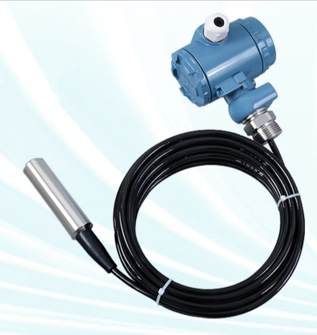


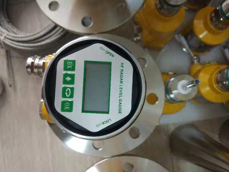
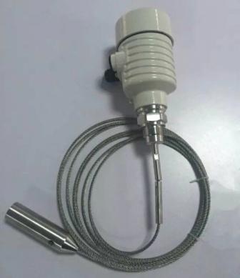
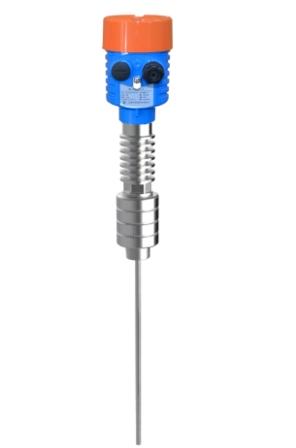
RD7X Guided Wave Radar Level Transmitter is a level measuring instrument based on the principle of time travel. Radar waves operate at the speed of light, and the operating time can be converted into level signals through electronic components. The probe emits high-frequency pulses and propagates along the cable or rod probe. When the pulses encounter the material surface, they are reflected back and received by the receiver inside the instrument, converting the distance signal into a material level signal.
The reflected pulse signal is transmitted along the cable or rod probe to the electronic circuit part of the instrument, and the microprocessor processes this signal to identify the echo generated by the microwave pulse on the material surface. The correct recognition of echo signals is completed by pulse software, and the distance D from the material surface is proportional to the time travel T of the pulse:
D=C×T/2
Where C is the speed of light
Since the distance E of the empty tank is known, the material level L is:
L=E-D
By inputting the empty tank height E (=zero point), full tank height F (=full range), and some application parameters, the application parameters will automatically adapt the instrument to the measurement environment. Corresponds to a 4-20mA output.
Measurement Explanation:
H - Measurement range
L - Empty tank distance
B - Top blind spot
E - Minimum distance from probe to tank wall
The top blind spot refers to the minimum distance between the highest material surface and the measurement reference point.
The bottom blind spot refers to a distance near the bottom of a cable that cannot be accurately measured.
There is a limited measurement distance between the top blind spot and the bottom blind spot. Only when the material is between the top blind zone and the bottom blind zone can reliable measurement of the level inside the tank be ensured.
Technical Description
Working frequency :100MHz~1.8MHz
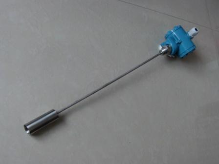
Measuring range: cable type 0~30m/rod, double rod, coaxial tube:0~6m
Repeatability:±2mm
Resolution:1mm
Precision:<0.1%
Sampling: echo sampling 55 times/s
Response speed:>0.2s(depending on the actual usage)
Output current signal:4~20mA
Communication interface: HART communication protocol
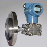
Process connection:G1½B Screw thread
DN50、DN80、DN100、DN150、DN200、DN250 Flange
Process pressure:-0.1MPa~2MPa
Power supply:24V DC(±10%)
Ripple voltage:1Vpp
Power consumption: max 22.5mA
Environmental conditions:-40℃~70℃
Anti-explosion:Exia ⅡC T6
Protection grade:IP67
Connection: instrument power supply and signal output share a core shielded cable (Two-wire)
Cable entry: two M20×1.5 or ½ NPT ( cable diameter:5~9mm)
The relationship between different categories of measured media and measurement distance