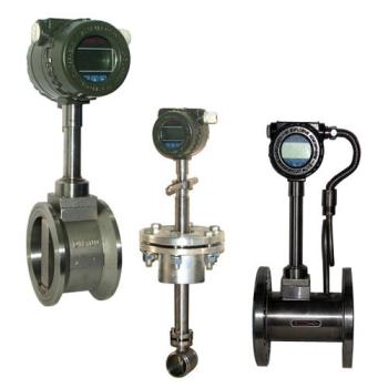


LZ metal tube float flowmeter (metal rotor flowmeter) is a variable area flowmeter based on float position measurement. The instrument adopts all-metal structure and modular conceptual design. It has the characteristics of small volume, small pressure loss, large range ratio (10:1), convenient installation and maintenance. It is widely used in flow measurement and process control under various complex and harsh environments, such as small flow rate, low flow rate and various harsh medium conditions. It can be used to measure the flow of liquid, gas and steam, especially suitable for low flow rate. Medium flow measurement with small flow rate. The instrument has various measurement forms for different user needs and different application occasions. It has on-site display and intelligent remote transmission, with pointer display, instantaneous flow, cumulative flow, liquid crystal display, upper and lower alarm output, cumulative pulse output, standard two-wire 4-20mA current output and other forms.
LZ metal tube float flowmeter (metal rotator flowmeter) adopts the international advanced Honeywell contactless magnetic sensor to detect the angle change of magnetic field, and is equipped with Motorola micro-processing system. It can realize liquid crystal indication, accumulation, remote transmission (4-20mA), pulse output, upper and lower limit alarm output and other functions. The intelligent signal transmitter has high precision and reliability. It has the characteristics of high cost performance, multi-parameter calibration, power-off protection and so on.
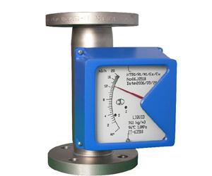
Structure and Principle
LZ metal tube float flowmeter (metal rotor flowmeter) consists of two parts: sensor (measuring tube and float) and signal transmitter (indicator). There are four kinds of contact material for sensor: stainless steel, Hastelloy, titanium and PTFE with stainless steel lining. Users can choose different contact material according to different process pressure and corrosive requirements of medium to meet the needs of pressure resistance and medium corrosion resistance of process. According to different measurement requirements, users can choose different combinations of indicators to achieve different measurement requirements. The specific indicator form and its corresponding functions are shown in the indicator type spectrum table.
When the measured medium passes through the conical measuring tube from bottom to top, the differential pressure on the upper and lower ends of the float forms an upward force. When the lifting force on the float is greater than the weight of the float immersed in the fluid, the float rises, the annulus area increases, the fluid velocity in the annulus decreases immediately, the differential pressure on the upper and lower ends of the float decreases, and the lifting force acting on the float decreases until the lifting force equals to that immersed in the fluid. When the weight of the float is medium, the float will stabilize at a certain height. The position of float corresponds to the flow rate of measured medium. When the float moves up and down with the medium, the magnetic field changes with the movement of the float. For the in-situ type, the rotating magnet in the in-situ indicator is coupled with the magnet in the float, and rotates. At the same time, the pointer is driven, and the flow rate at this time is indicated by the dial. For the intelligent type, the change of magnetic field is transformed into electrical signal by a solid-state magnetic sensor in the intelligent indicator, and the flow and cumulative flow are displayed by A/D conversion, microprocessor, D/A output and LCD liquid crystal display.
Features
Modular combination design, easy maintenance, normal use and maintenance-free.
suitable for small diameter and low flow rate, reliable operation, small maintenance and long service life.
With a wide flow range of 10:1, the requirement for downstream straight pipe section is not high.
Uniaxial and non-contact new magnetic coupling structure, more stable signal transmission.
Dual-line, large-screen LCD display instantaneous and cumulative flow, with backlight.
Intelligent power-down protection, data backup and recovery.
All-metal structure, anti-seismic, anti-pressure, anti-temperature, anti-corrosion.
Short stroke, total height 250mm, design and installation more convenient.
Technical Parameters
Measurement range: water (20 ℃) 5-200000 l/h; air (0.1013 MPa 20 ℃) 0.03-4000 m3/h.
Range ratio: 10:1.
Accuracy class: 1.5 (Special Type 1.0)
Operating pressure: DN15, DN25 and DN50 are PN4.0MPa(MAX 10MPa). DN80 and DN100 are PN1.6MPa(MAX 6.4MPa).
Medium Temperature: - 40 ~300 ℃
Medium Viscosity: DN15:_<5mPa.s (F15.1-F15.3); _<30mPa.s (F15.4-F15.8); DN25:_<250mPa.s; DN50-DN150:_<300mPa.s
Ambient temperature: liquid crystal type: - 40 ~85℃ pointer type: - 40 120℃.
Connection: Flange (manufactured according to DIN2501 or user-supplied flange standard); Thread Connection Type: DIN11851 or user-specified.
Instrument height: 250mm.
Electrical connection: M20*1.5.
Power supply: 24VDC two-wire 4-20mA or 85-265VAC 50/60Hz (remote transmission type); AC type: 220VAC (85-265VAC).
Alarm output: upper or lower limit instantaneous flow alarm relay output (maximum contact capacity 5A,250VAC) or collector open circuit output (maximum internal impedance 100MA,30VDC 100).
Pulse output: cumulative pulse output with a minimum interval of one pulse per 10 seconds (AC type) or one pulse per 50 milliseconds.
LCD Display: Double-row LCD Display, Display Instantaneous Flow and Accumulated Flow.
Protection class: IP65.
Ordering Codes
|
Model |
Basic Code |
Description |
|||||||
|
LZ |
|
|
|||||||
|
Measurement tube structure |
GS1 |
|
lower-upper path |
||||||
|
GS2 |
|
lower-upper level path |
|||||||
|
GS3 |
|
Lower level in and upper level out |
|||||||
|
GS4 |
|
Right in left out |
|||||||
|
GS5 |
|
Left in right out |
|||||||
|
Wetted materials |
R0 |
|
0Cr18Ni2Mo2Ti |
||||||
|
R1 |
|
1Cr18Ni9Ti |
|||||||
|
RP |
|
PTFE |
|||||||
|
T1 |
|
titanium alloy |
|||||||
|
R3 |
|
316L |
|||||||
|
Pipe diameter |
15 |
|
DN15 |
||||||
|
25 |
|
DN25 |
|||||||
|
50 |
|
DN50 |
|||||||
|
80 |
|
DN80 |
|||||||
|
100 |
|
DN100 |
|||||||
|
150 |
|
DN150 |
|||||||
|
200 |
|
DN200 |
|||||||
|
Additional structure |
T |
|
|
||||||
|
Z |
|
Damping type |
|||||||
|
G |
|
High temperature type |
|||||||
|
Y |
|
High pressure type |
|||||||
|
Display type |
M1 |
|
In-situ indicator, mechanical indication of instantaneous flow |
||||||
|
M2 |
|
Power supply type, mechanical indication instantaneous flow, LCD display instantaneous/cumulative flow |
|||||||
|
M3 |
|
Power supply type, no mechanical indication, LCD display instantaneous/cumulative flow |
|||||||
|
Power supply |
Z |
|
M1 Indicator Only |
||||||
|
A |
|
220VAC, 4-20mA Output |
|||||||
|
B |
|
Battery power supply, no output |
|||||||
|
C |
|
24VDC, two-wire power supply, 4-20mA output |
|||||||
|
D |
|
24VDC, three-wire and four-wire power supply, 4-20mA output |
|||||||
|
Explosion-proof mark |
i |
|
CT5 square Housing |
||||||
|
d |
|
Diibt 4 round Housing |
|||||||
|
Alarm or Pulse Output |
K0 |
No alarm or pulse output |
|||||||
|
K1 |
Upper limit alarm or one pulse output |
||||||||
|
K2 |
Lower limit alarm or one pulse output |
||||||||
|
2K3 |
Upper and Lower Limit Alarm or Double Pulse Output |
||||||||