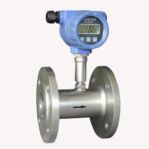


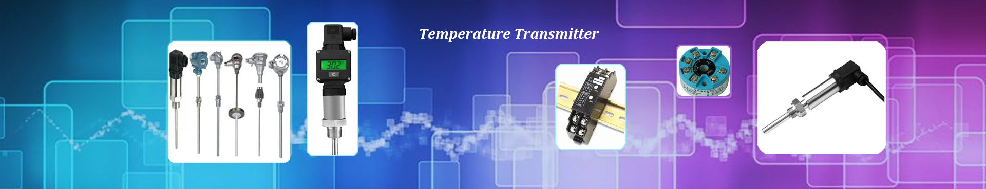
Model LWG-Q Gas Turbine Flow Sensor is a new generation of high precision and high reliability gas precision metering instrument, which has absorbed advanced technology of flow meters at home and abroad and optimized design. It integrates theory of gas mechanics, fluid mechanics and electromagnetics. It has excellent low pressure and high pressure metering performance, multiple signal output modes and low sensitivity to fluid disturbance. This kind of turbine flow product does not have the function of on-site display, and only transmits the flow signal by means of pulse signal. The instrument is cheap, highly integrated and compact. It is especially suitable for use with secondary display, PLC, DCS and other computer control systems.
Features
Low starting flow, up to 0.5m3/h, suitable for trade settlement.
High accuracy, generally up to (+1.5%R,+1.0%R).
Good repeatability, short-term repeatability can reach 0.05% - 0.2%.
Real-time compensation of temperature and pressure, direct display of flow rate in standard state.
High quality alloy turbine, with higher steady flow and corrosion resistance.
High-quality special bearings, long service life.
The metering chamber is isolated from the ventilation chamber, which ensures the safety of the instrument.
Wide flow range (Qmax/Qmin (> 20:1), good repeatability, high accuracy (up to 1.0 grade), low pressure loss, low starting flow, up to 0.6m3/h.
Instrument classification
LWG-Q series gas turbine flowmeters can be classified into three categories according to their functions: N-type and A-type (gas turbine flow sensor/transmitter); B-type and C-type (intelligent integrated gas turbine flowmeter); D-type (intelligent temperature and pressure compensation integrated gas turbine flowmeter).
1) Type N and Type A (Gas Turbine Flow Sensor/Transmitter)
This kind of turbine flow product does not have the function of on-site display, only transmits the flow signal far away. Flow signal can be divided into pulse signal or current signal (4-20mA). Instrument is cheap, highly integrated and compact, especially suitable for use with secondary display, PLC, DCS and other computer control systems. According to different output signals, the products can be divided into LWG-Q-N and LWG-Q-A.
|
|
LWG-Q-N |
LWG-Q-A |
|
Display mode |
No Display |
No Display |
|
Output signal |
Three-wire Pulse Output, High Level (>8V), Low Level (<0.8V) |
operating condition 4-20mA |
|
Power supply |
12 or 24VDC |
24VDC |
Application occasion: It can be used as a collection instrument of flow signal under working condition, and it can transmit the flow signal to the upper computer far away.
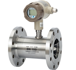
2) Type B and Type C (Intelligent Integrated Gas Turbine Flowmeter)
Integrative intelligent instrument, using double-row LCD field display, has the obvious advantages of compact mechanism, intuitive and clear reading, high reliability, not disturbed by external power supply, lightning resistance, low cost and so on. The turbine flowmeter can be divided into LWG-Q-B type and LWG-Q-C type according to power supply mode and remote signal output.
|
|
LWG-Q-B |
LWG-Q-C |
|
Display mode |
Simultaneously display instantaneous flow and total cumulative flow |
Simultaneously display instantaneous flow and total cumulative flow |
|
Output signal |
None |
operating condition 4-20mA, pulse |
|
Power supply |
3V Lithium Battery Power Supply (For more than 4 consecutive years) |
24VDC |
Application occasion: As an industrial control instrument, it can be used in the field where the temperature and pressure are relatively stable. In the field where the temperature and pressure are relatively stable, the user can calculate the standard flow rate by himself according to the gas equation indicated by the instrument.
3) Type D (Intelligent Temperature and Pressure Compensation Integrated Gas Turbine Flowmeter)
LWG-Q-D gas turbine meter has built-in temperature, pressure sensor and intelligent flow totalizer. The real-time collected flow, temperature and pressure signals are compensated by micro-processing unit according to the gas equation, and the compression factor is automatically corrected. Then the volume flow in the standard state is visually displayed.
※Standard state flow (standard state flow) refers to the flow of gas at 20℃ and atmospheric pressure.
|
Display mode |
At the same time, the instantaneous flow rate, daily cumulative flow rate, total cumulative flow rate, temperature, pressure, battery power and other data under the standard state are displayed. |
|
Output signal |
Standard condition 4-20 mA, operating condition pulse signal, standard condition pulse signal, IC card signal, RS485 communication protocol |
|
Power supply |
With built-in lithium battery and 24 VDC dual power supply mode, when users do not need any signal output function, they do not need to supply external power to the instrument 24VDC. The instrument automatically switches to the built-in lithium battery power supply. The battery power can work continuously for more than three years. |
Application: Precise measurement or trade settlement.
Technical Parameters
|
Instrument caliber (mm) and connection |
25, 40, 50, 65, 80, 100, 125, 150, 200, 250, 300 flanged connections. 25, 40 can be connected by thread |
|
|
Accuracy class |
±1.5%R,±1%R,±0.75%R(Special customization) |
|
|
Range ratio |
1:10:1:20:1:30 |
|
|
Instrument material |
body: 304 stainless steel; impeller: anti-corrosion ABS or high quality aluminum and gold; display: cast aluminum |
|
|
Medium temperature |
-30℃~+80℃ |
|
|
Ambient condition |
TEMP:-20℃~+60℃,relative humidity 5%~90%, atmospheric pressure 86~106KPa |
|
|
Output signal |
Sensor: Pulse Frequency Signal, Low Level < 0.8V, High Level < 8V
Transmitter: Two-wire 4 to 20mADC Current Signal |
|
|
Power supply |
Sensors: +12VDC, +24VDC (optional) Transmitter: +24VDC Local display type: instrument with 3V lithium battery |
|
|
Signal transmission line |
STVPV3 x 0.3 (three-wire) and 2 x 0.3 (two-wire) |
|
|
Transmission distance |
≤1000m |
|
|
Signal line interface |
M20*1.5 (F) |
|
|
Protection class |
IP65 |
Measurement range and operating pressure
|
Caliber |
Model |
Standard range |
Extended range (m3/h) |
Pressure rating |
Connection |
||
|
DN25 |
LWG-Q-25□ |
|
—— |
W3 |
0.5-4 |
4.0 |
Flange (thread) |
|
|
—— |
W4 |
0.7-7 |
4.0 |
|||
|
|
—— |
W5 |
1.5-15 |
4.0 |
|||
|
S1 |
3-30 |
W1 |
1.5-30 |
4.0 |
|||
|
S2 |
4-40 |
W2 |
2-40 |
4.0 |
|||
|
DN40 |
LWG-Q-40□ |
S1 |
5-50 |
W1 |
2.5-50 |
4.0 |
Flange (thread) |
|
S2 |
8-80 |
W2 |
4-80 |
4.0 |
|||
|
DN50 |
LWG-Q-50□ |
S1 |
10-100 |
W1 |
5-100 |
4.0 |
Flange |
|
S2 |
15-150 |
W2 |
8-150 |
4.0 |
Flange |
||
|
DN65 |
LWG-Q-65□ |
S |
15-200 |
W |
10-200 |
1.6 |
Flange |
|
DN80 |
LWG-Q-80□ |
S |
15-300 |
W1 |
10-300 |
1.6 |
Flange |
|
W2 |
15-350 |
1.6 |
Flange |
||||
|
DN100 |
LWG-Q-100□ |
S |
20-400 |
W1 |
15-400 |
1.6 |
Flange |
|
W2 |
20-500 |
1.6 |
Flange |
||||
|
DN125 |
LWG-Q-125□ |
S |
20-800 |
W1 |
18-800 |
1.6 |
Flange |
|
W2 |
20-900 |
1.6 |
Flange |
||||
|
DN150 |
LWG-Q-150□ |
S |
50-1000 |
W1 |
25-1000 |
1.6 |
Flange |
|
W2 |
50-1200 |
1.6 |
Flange |
||||
|
DN200 |
LWG-Q-200□ |
S |
150-2000 |
W |
80-2500 |
1.6 |
Flange |
|
DN250 |
LWG-Q-250□ |
S |
200-3000 |
W |
150-3500 |
1.6 |
Flange |
|
DN300 |
LWG-Q-300□ |
S |
250-4000 |
W |
200-4000 |
1.6 |
Flange |
Ordering Codes
Users should select the type and specification of flowmeter according to nominal pressure of pipeline, maximum pressure of medium, temperature of medium, composition of medium, flow range and signal output requirement.
|
Model |
description |
|||||
|
LWG-Q— |
□ |
—□ |
□ |
/□ |
/□ |
|
|
Meter Type |
N |
|
|
|
|
Sensor type: +12V or 24V power supply, output three-wire pulse signal |
|
A |
Transmitter type: +24V power supply, output 2-wire 4-20mA |
|||||
|
B |
Intelligent: Lithium battery power supply, Local display without signal output |
|||||
|
C |
Intelligent: +24V power supply, Local display and output 2-wire 4-20mA |
|||||
|
D |
Intelligent: Integration of temperature and pressure compensation, Local display and remote transmission of signals |
|||||
|
Caliber & range |
25 |
DN25mm |
||||
|
40 |
DN40 mm |
|||||
|
50 |
DN50 mm |
|||||
|
65 |
DN65 mm |
|||||
|
80 |
DN80 mm |
|||||
|
100 |
DN100 mm |
|||||
|
125 |
DN125 mm |
|||||
|
150 |
DN150 mm |
|||||
|
200 |
DN200 mm |
|||||
|
250 |
DN250 mm |
|||||
|
300 |
DN300 mm |
|||||
|
Range |
W(x) |
To extend the range, please refer to Table 2 on Px page to select |
||||
|
S(x) |
To extend the range, please refer to Table 2 on Px page to select |
|||||
|
Body material |
S |
Stainless steel |
||||
|
L |
Aluminum alloy |
|||||
|
Display material |
S |
Anticorrosive ABS |
||||
|
L |
Aluminum alloy |
|||||