


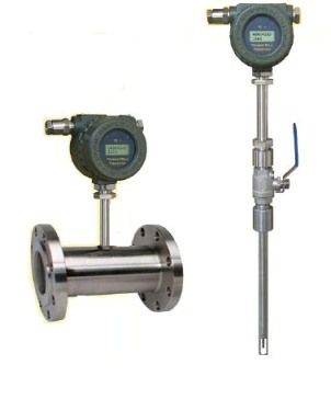
The thermal mass flowmeter is designed and manufactured on the basis of Kim's law, i.e. the principle of thermal diffusion. The so-called Kim's Law refers to the number of fluid molecules flowing through the superheat source in direct proportion to the amount of heat dissipation. There are two ways to realize this principle: one is the constant power method, the other is the constant temperature difference method. According to Gene's Law, mass flow Q can be obtained from the ratio of heating power to temperature difference of heat source. In practical work, we fix any parameter of heating power or temperature difference to measure the quality of fluid. The former is constant power method and the latter is constant temperature difference method. The thermal gas mass flowmeter manufactured by our company guarantees the consistency and reliability of the instrument through the application of the above principles and professional technology. The instrument has two sensors, one is the heat source and the other is the temperature of the medium. When the fluid flows, the molecular weight of the fluid flowing through the two sensors is proportional to the heat loss of the heat source. According to this relationship, the instrument calculates the mass flow rate of the gas through the electronic module. Since the instrument measures the mass of molecules in the fluid, it has nothing to do with the temperature and pressure of the medium, and the measured flow rate is the mass flow rate.
Features
Direct mass flow measurement without temperature and pressure compensation.
High precision measurements can also be obtained at low range.
Maximum range ratio to 1:1000, with leak detection function.
Short response time.
Pressure loss is negligible.
No movable parts, using aseismic design.
Easy installation and high economy.
Repeatability depends on the exact installation location.
Flow measurement for large caliber and regular pipes.
With Replacement Sealing Device, Online Installation and Replacement.
Multiple diagnostic functions.
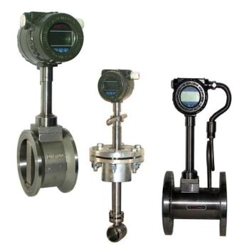
Integrated or split type optional.
Setting of Different Gas Coefficient and Matching of Intelligent Digital Flow Totalizer
Application
Application in metallurgical industry: Blast furnace gas, coke oven gas measurement, steel aeration measurement, steel rolling gas measurement and control, process control of hydrogen, oxygen, nitrogen and other gases such as heat treatment quenching furnace, and various gases in steel plant to measure air, N2, O2, H2, CH4, He, CO2, NH3, natural gas etc. Advantages: simple installation, easy cleaning, high range ratio, low pressure loss, high accuracy.
Petrochemical industry applications: torch gas emission, flue gas, ammonia measurement in fertilizer plants. Advantages: Good small flow sensitivity, high range ratio, easy disassembly and cleaning.
Power industry applications: measurement of primary and secondary air in power plants; monitoring of SO2 and NOX emissions from flue gas exhaust, measurement of gas-assisted and preheated air supply in boilers, control of pulverized coal combustion process and hydrogen measurement of steam turbines in power plants when hydrogen is generally used as cooling material. Advantages: No moving parts, no pipeline blockage, high cost performance, low pressure loss, high range ratio.
Glass, ceramics and building materials industry applications: gas furnace intake control, Control of Hot Air Flow from Vertical Mill in Cement Industry. Advantages: Direct mass flow monitoring, high accuracy and calibration according to actual components.
Food and beverage industry, pharmaceutical industry applications: carbon dioxide treatment in breweries, waste gas flow monitoring in fermentation containers, fresh air addition in food processing operations, hot air flow monitoring in bottle disinfection in pharmaceutical industry. Advantages: Excellent low flow sensitivity, direct mass flow monitoring, high accuracy.
Application of water, wastewater and water treatment: measurement of biogas and ventilated air, measurement of air flow in aeration tank. Advantages: dirt resistance, dust resistance, easy installation, easy disassembly and cleaning.
Manufacturing Applications: Compressed Air Measurement, Leak Point Detection, Ratio of N2, O2 and Ar in Air Separation Unit, Fuel Cell Plant Gas Flow Measurement, Laboratory High Purity Gas Measurement. Advantages: no temperature and pressure compensation, excellent low flow sensitivity, mass flow monitoring, High range ratio, low pressure loss.
Technical Parameters
|
Measuring Medium |
Various gases (except acetylene) |
|
|
Caliber Range |
DN10~100mm(Full tube type) |
DN80~6000mm(Insertion type) |
|
Velocity Range |
0.5~100Nm/s |
|
|
Accuracy |
±1.0% |
|
|
Operating Temperature |
Sensors: Normal temperature type - 10 ~ 200 ℃, High temperature type: - 10 ~ 350 ℃, Converter: - 20 ~ 45 ℃ |
|
|
Operating Pressure |
Medium pressure ≤10Mpa |
Medium pressure ≤2.5Mpa |
|
Power Supply |
Integrated(DC 24V or AC220V≤18W)Split-type(AC220V≤19W) |
|
|
Speed Of Response |
1S |
|
|
Output Signal |
4~20mA (Photoelectric Isolation, Max Load 500Ω) RS485(Photoelectric Isolation) , Hart protocol |
|
|
Pipe Material |
Carbon steel, stainless steel, plastics, etc. |
|
|
Display |
LCD |
|
|
Show Contents |
mass flow, Standard condition Volume flow, Cumulative flow, standard time, Cumulative running time, medium temperature, standard velocity, etc. |
|
|
Protection Class |
IP67 |
|
|
Sensor Material |
Stainless steel |
Stainless steel, carbon steel |
Note:
1. If the medium pressure is greater than 4MPa, it should be customized through consultation with the manufacturer.
2. The plug-in process is connected by locking device/ball valve, and the pipeline process is connected by flange or thread.
3. The expanding range of flow rate of medium measured by the product can reach 0.1-100Nm/S. From this, the flow measurement range of products with different pipe diameters can be deduced. The formula is: flow rate=(flow rate*(pipe diameter mm)²)/353.8.
Upper Limit Of Range (Scalable, unit: Nm³/h)
|
Caliber(mm) |
Air |
Nitrogen(N2) |
Oxygen (O2) |
Hydrogen(H2) |
|
15 |
65 |
65 |
32 |
10 |
|
25 |
175 |
175 |
89 |
28 |
|
32 |
290 |
290 |
144 |
45 |
|
40 |
450 |
450 |
226 |
70 |
|
50 |
700 |
700 |
352 |
110 |
|
65 |
1200 |
1200 |
600 |
185 |
|
80 |
1800 |
1800 |
900 |
280 |
|
100 |
2800 |
2800 |
1420 |
470 |
|
125 |
4400 |
4400 |
2210 |
700 |
|
150 |
6300 |
6300 |
3200 |
940 |
|
200 |
10000 |
10000 |
5650 |
1880 |
|
250 |
17000 |
17000 |
8830 |
2820 |
|
300 |
25000 |
25000 |
12720 |
4060 |
|
400 |
45000 |
45000 |
22608 |
7200 |
|
500 |
70000 |
70000 |
35325 |
11280 |
|
600 |
100000 |
100000 |
50638 |
16300 |
|
700 |
135000 |
135000 |
69240 |
22100 |
|
800 |
180000 |
180000 |
90432 |
29000 |
|
900 |
220000 |
220000 |
114500 |
77807 |
|
1000 |
280000 |
280000 |
141300 |
81120 |
|
1200 |
400000 |
400000 |
203480 |
91972 |
|
1500 |
600000 |
600000 |
318000 |
101520 |
|
2000 |
700000 |
700000 |
565200 |
180480 |
Standard condition:TEMP 20℃,PRESS 101.325KPa
Unit Options for Instantaneous Flow: Nm³/h, L/h, L/min, t/h, t/min, kg/h and kg/min.
Installation Method
Insert installation:
1. Position determination: Keep away from elbows, solenoid valves and other parts to ensure steady flow field.
2. Welding base: drill a circular hole of 22mm on the pipeline and weld the welding base.
3. Installation Instrument: Insert the locking head into the probe rod and tighten it with a wrench after confirming the insertion depth.
4. Recommends that users use Globe valve in the selection, Easy disassembly. Especially in the media sites which are harmful to human body.
5. Diameter less than DN300, insertion depth 1/2D+15mm. Diameter DN300~DN1000, insertion depth 1/4D+15mm. Diameter above DN1000, insertion depth 1/8D+15mm.
Pipe section installation method:
Horizontal and vertical installation. The special flange is welded with the front and
rear straight pipe sections, and then the front and rear straight pipe
sections, sealing gaskets and instruments are clamped with double-headed bolts
to form a whole. Then install
this set of components on the pipeline. When installing, attention should be
paid to the direction marked on the instrument should be consistent with the
direction of the fluid.
Ordering Codes
|
Model |
Description |
|
|
LRS |
|
Thermal Gas Mass Flowmeter |
|
Sensor Type |
C |
Insertion type |
|
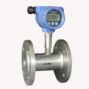
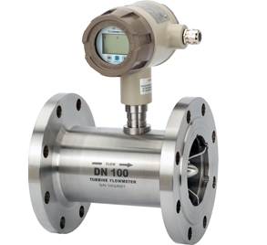
FG |
Flange pipe section type |
|
|
LG |
Thread pipe section type |
|
|
J |
Clamping type |
|
|
Caliber (mm) |
Pipe inner diameter :10-6000(mm) |
|
|
The square pipe provides side length:25*25-2000*2000 |
||
|
Material |
A |
316SS |
|
B |
304SS |
|
|
C |
201SS |
|
|
D |
Anticorrosive coating |
|
|
E |
Other materials |
|
|
PRESS (Mpa) |
S |
<1.6 |
|
M |
1.6~2.5 |
|
|
H |
< 4 |
|
|
TEMP (℃) |
Ⅰ |
-40~200 |
|
Ⅱ |
-40~450 |
|
|
Output Signal |
1 |
4-20mA |
|
2 |
RS485 |
|
|
3 |
pulse |
|
|
4 |
Relay N.O. contact |
|
|
5 |
4-20mA+HART protocol |
|
|
Power Supply |
DC |
24VDC |
|
AC |
220VAC |
|
|
Display |
J |
Local display |
|
S |
Split display |
|